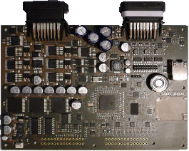
Inputs/Outputs
- 6× 10 A (PWM) High side switch
- 1× H-Bridge (10 A)
- 6× Digital output (2 A)
- 8× Digital output (100 mA)
- 16× Digital input (min. 8× interrupt IF)
- 12 channel ADC (0 – 20 V)
- 4× DA converter (0 – 12 V)
Board programming
- FreeRTOS™ + C libraries & drivers
- Simulink® Embedded Coder
- Automatic C code generation from graphical models
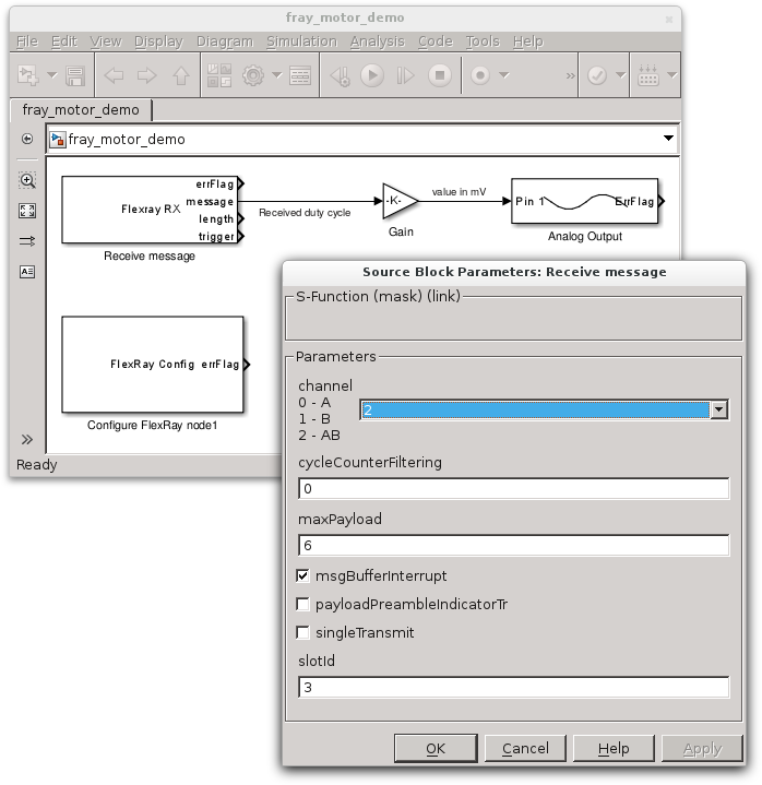
- Simulink blocks for all I/Os & FlexRay
- Documentation
- Serial line command line interface (reference)
MCU for Safety Critical Applications
- ARM® Cortex™ – R4F 32-bit RISC CPU, up to 180 MHz
- Dual CPU running in lockstep
- Texas Instruments TMS570LS3137
- 256 kB RAM, 3 MB FLASH
Communication interfaces
- 3× CAN
- 1× FlexRay (2 channels)
- Ethernet
- LIN

Contacts
- Zdeněk Hanzálek – project lead
- Pavel Píša – HW/SW developer
- Michal Sojka – SW developer
- Petr Porazil – MCU and chips selection, HW design coarchitect with Pavel Pisa, PCB design, fixing of routine works flaws of CTU students etc.
- PiKRON s.r.o. – provided embedded systems know-how, time, laboratory space, tools and equipment used for hardware bring-up, SDRAM timing, powermanagement testing, CAN bus testing and fixups, boot code fixup, advises to CTU workers etc.

