TMS570LS3137


Documentation
- Main TI page containing datasheets.
- TI TMS570 related forum
- TMS570 Wiki
- Media:Studim_procesoru.pdf Notes from documentation (in Czech language)
Programming
Tools recommended by TI for programming of this microcontroller:
- Code Composer Studio (runs on Win and Linux)
- HalCoGen (for WIn only, but also runs quite well in Wine)
FreeRTOS
Installation is easy, simply create new project in HalCoGen
- New -> Project
- Select Family:TMS570LS31x
- Select Device: TMS570LS3137ZWT_FREERTOS
All necessary files will be added into project automaticaly.
Hardware
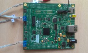
Developement board we are using: TMS570LS31x_HDK_Kit
SCI port
We have connected serial port on Expansion Connector P3 (see HDK documentation) pin W3 and N2. TX is connected to N2 pin and RX to W3 pin. This brings us consequences as both pins are mutexed.
When you want to use SCI, you have to set few things in HalCoGen.
- Enable driver SCI (not LIN or SCI2 driver)
- In tab PINMUX select SCI and check conflict with other drivers
- In tab SCI choose and set data format.
When you want use interrupts in adittion, do the following:
- In tab VIM Channel 64-95 select interrupt 64: SCI level0 interrupt for high level interrupt or 74: SCI Level1 for low level interrupt
- In SCI tab enable TX and/or RX interrupt and select High or Low.
- In your code enable IRQ using _enable_IRQ() function, than enable notification using sciEnableNotification() function.
- Implement notification callback sciNotification() in notificatin.c
In your code don't forget to initialize sci using sciInit() function.
Debug over JTAG
XDS100v2 JTAG Interface from Ti
The XDS100v2 is equipped with Ti specific 14-pin JTAG connector. Next cable wires placement allows to use it with TMS570LS31x_HDK_Kit or other device with ARM JTAG pin placement.
| 14 pin Ti | 20 pin ARM | ||
|---|---|---|---|
| 1 | TMS | TMS | 7 |
| 2 | TRST | NTRST | 3 |
| 3 | TDI | TDI | 5 |
| 4 | DIS | GND | 6 |
| 5 | VD | VREF | 1 (2) |
| 6 | NC | -- | |
| 7 | TDO | TDO | 13 |
| 8 | GND | GND | (4) |
| 9 | RTCK | RTCK | 11 |
| 10 | GND | GND | 8 (12) |
| 11 | TCK | TCK | 9 |
| 12 | GND | GND | 10 (14) |
| 13 | EMU0 | ||
| 14 | EMU1 | ||
Setup XDS100v2 on Linux
By default the device (if nothing more connected then /dev/ttyUSB0) is added with permissions 664 with
root as user and group. You access the device we need write access for current user. To do so we need
to create a new udev rules:
sudo nano /etc/udev/rules.d/45-pes-rpp.rules
And add line:
ACTION=="add", SUBSYSTEM=="usb", ATTR{idVendor}=="0403", ATTR{idProduct}=="a6d0", MODE="0660", GROUP="plugdev"
Then reload udev rules with:
sudo udevadm control --reload-rules
You can check device properties like idVendor or idProduct with the following command:
udevadm info -a -p $(udevadm info -q path -n /dev/ttyUSB0)
RS232 communication setup
Connect serial communication pins to computer's RS232 port or to USB through a FTDI adapter. If using RS232 port the
device should be /dev/ttyS0, if using FTDI it should be something like /dev/ttyUSBx
(check dmesg for details).
Make sure minicom or similar terminal program is installed:
sudo apt-get install minicom
Then configure minicon:
sudo minicom -s
And use the following configuration "9600 81N":
Serial Device         : /dev/ttyS0
Lockfile Location     : /var/lock
Callin Program        :
Callout Program       :
Bps/Par/Bits          : 9600 8N1
Hardware Flow Control : No
Software Flow Control : No
Start terminal session and type HELP command to test communication.