Introduction to TmoteSky: Difference between revisions
| Line 129: | Line 129: | ||
REFVOLT_LEVEL_2_5 = 1, // reference voltage of 2.5 V | REFVOLT_LEVEL_2_5 = 1, // reference voltage of 2.5 V | ||
== ZigBee communication speed == | |||
This is just a mail read on the tinyos help forum, written by [[mailto:whelanmj@clarkson.edu Matthew J Whelan]] | This is just a mail read on the tinyos help forum, written by [[mailto:whelanmj@clarkson.edu Matthew J Whelan]] | ||
Revision as of 22:00, 17 January 2007
NesC philosophy
Just a little tutorial of NesC programmation' structure and an analyse of the most used app on TMote module : OscilloscopeRF.
This article was written by Nicoo.
A representation of data code
A description of a possible representation of data code for NesC, is like article A Holistic Approach to Networked Embedded Systems.
NesC allow to split c source code in some module and make dialog them throw interface, like this schematic :
- When a module use interface, it means that it can call a function by this interface, or an even on this mudule can be tell by this interface.
- When a module provide an interface, it means module provide all functions defined by interface.
- You can see when an module provides several interface, you are not obliged to connect all interface to make run the module.
- When a module uses or provides several same interface, you have to rename it (like SendMsg in OscilloscopeM) or use the array notation (like SendMsg in GenericComm).
Learn by a sample: OscilloscopeRF
OscilloscopeRF is a very usefull sample program because it can make an acquisition on a sensor and send value throw Zigbee, to an other module where is running TOSBase application.
This is the main wiring of the app :
- Module main, provided by tinyos, use interface StdControl, so OscilloscopeM and Timer must implement functions Init(), Start() and Stop(). When you put a supply on a mote, Init() and Start() are called.
- Module Timer and OscilloscopeM are both connected to Main StdControl, so the code in both module will be exectuted in parallel; you dont care about multi-thread, tinyos think for you.
Communication between Mote
As you can see on the picture, communication module GenericComm is very easy to implement.
- StdControl interface must be used; you have to call it Init() and Start() before all.
- Data can be multiplexed. GenericComm has 256 interface SendData and ReceiveData. For example, OscilloscopeM is wired on interface SendData[10], ReceiveData[11] and ReceiveData[32]. Concretely this multiplexing is just a byte in the header of paquets.
- If you send data on SendData[10], on a second mote, you have to wire the ReceiveData[10].
When you listen paquets on cygwin (see commands below), struture of paquets looks as (uncomplete):
- Group @ : when you develop an application on mote, to avoid conflict, you have to choose a group address. When mote receive paquets with an other group @ - from an other application - the paquet will be rejected. This @ can be modified in AM.h, by default, it's Oxffff.
- N# : is byte is auto-incremented for each paquet, it can be used if paquets are unsequenced.
- Interface : it is the byte described before, it represents one of interface on module GenericComm.
Nota: If you want to ajust yourself the size of DATA, you have to take care about am.h :
#ifndef TOSH_DATA_LENGTH
#define TOSH_DATA_LENGTH 29
#endif
29 byte seem to be the maximum value for TOSH_DATA_LENGTH.
Encapsulation of data
OscilloscopeRF app use the encapsulation for send several data in one paquet :
- Mote id : is a constant value. In the original sample, this value is TOS_LOCAL_ADDRESS described in tos.h. After my modification, this is described by SOURCEMOTEID in OscilloscopeM.nc.
- Channel : at origin is just a constant value set to 1. After my modification, Channel represent number of analog input.
- N# last sample : an auto-incremental value, set to 0 when power is on. You can reset this value by sending a broadcast msg on channel 32.
- Data : by default there is 10 values by paquets, so value are buffered before be sent.
Data acquisition
Data acquisition works throw the module DemoSensorC. This module is very trivial :
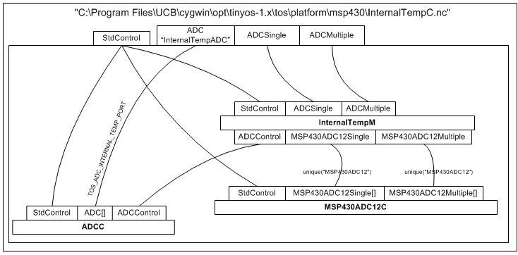
But behind it, it's darker :
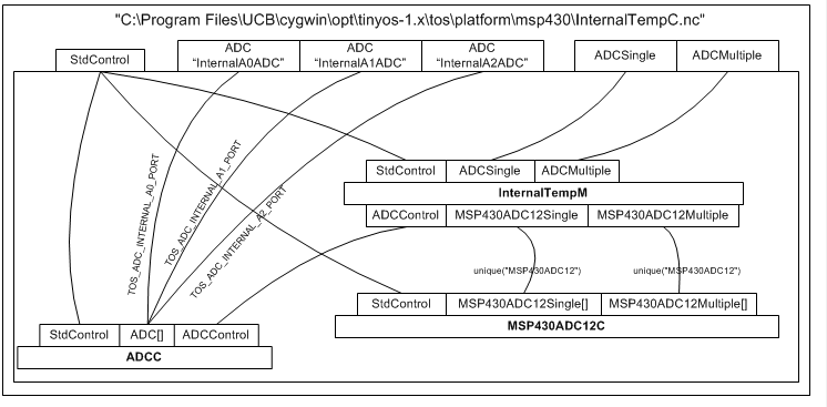
And after my modification, it looks like :
Now some explanations. First, you can see that module ADCC have several interface ADC (it is quoted by ADC[]). Before ask for acquistion you have to bind theses interface to a hardware input. It's the role of the module InternalTempM. By the interface ADCControl, it calls the bind fonction like this :
   ok2 = call ADCControl.bindPort(TOS_ADC_INTERNAL_A0_PORT,
                                 TOSH_ACTUAL_ADC_INTERNAL_A0_PORT);
Constant used are defined in InternalTemp.h :
TOS_ADC_INTERNAL_A0_PORT = unique("ADCPort"),
TOSH_ACTUAL_ADC_INTERNAL_A0_PORT = ASSOCIATE_ADC_CHANNEL(
                                           INPUT_CHANNEL_A0,
                                           REFERENCE_VREFplus_AVss,
                                           REFVOLT_LEVEL_2_5),
All means that the function unique("ADCPort") will find a free ADC interface on module ADCC, and bind it to the INPUT_CHANNEL_A0, with the written configuration. Now throw interface ADCC.ADC[TOS_ADC_INTERNAL_A0_PORT] you can call a getData() to ask for an aquisition.
- For my project, I need tu use 3 input, so I have make 3 bind on ADCC, and wired 3 interfaces ADC.
- Possible configurations are defined in MSP430ADC12.h, this is an extract of the file :
  INPUT_CHANNEL_A0 = 0,                    // input channel A0
  INPUT_CHANNEL_A1 = 1,                    // input channel A1
  INPUT_CHANNEL_A2 = 2,                    // input channel A2
  INPUT_CHANNEL_A3 = 3,                    // input channel A3
  INPUT_CHANNEL_A4 = 4,                    // input channel A4
  INPUT_CHANNEL_A5 = 5,                    // input channel A5
  INPUT_CHANNEL_A6 = 6,                    // input channel A6
  INPUT_CHANNEL_A7 = 7,                    // input channel A7
  EXTERNAL_REFERENCE_VOLTAGE = 8,          // VeREF+ (input channel 8)
  REFERENCE_VOLTAGE_NEGATIVE_TERMINAL = 9, // VREF-/VeREF- (input channel 9)
  INTERNAL_TEMPERATURE = 10,               // Temperature diode (input channel 10)
  INTERNAL_VOLTAGE = 11                    // (AVcc-AVss)/2 (input channel 11-15)
  REFVOLT_LEVEL_1_5 = 0,                    // reference voltage of 1.5 V
  REFVOLT_LEVEL_2_5 = 1,                    // reference voltage of 2.5 V
ZigBee communication speed
This is just a mail read on the tinyos help forum, written by [Matthew J Whelan]
The maximum theoretical data rate of the CC2420 is 250kbps.  However to achieve anywhere
near this rate, you have to carefully schedule transmissions to avoid packet collisions
and loss.  I can't quote you any rates achievable using any of the standard radio libraries
or base applications, as I have had some problems with transparency of the code and would
rather write my own than try to figure out someone elses.  To be honest, I have had a
problem using the base applications provided with TinyOS when sending at a high rate
from multiple motes and I would very much recommend that you write your own base
application if you intend to push a lot of data across the radio.

Using my own base application, I have recieved data from 10 motes, sending 99byte packets
at a rate of 7 packets per second (approx. 700bytes/mote/sec or 70kbps total) with virtually
no packet loss at all (nearly all motes have 100% success after 5-10 minutes).  I am
convinced that the radio can handle MUCH HIGHER rates than that, even the 250kbps, though
it takes careful software development and knowledge of the CC2420 chip.   I need to invest
in more motes before I push my network to the limits in terms of data rate, but I thought
that I would let you know that the numbers you have seen have grossly underestimated the
radio data rate.


