Eurobot 2007 - Robot Recycling Rally
Technical Specification
Competition Objectives
Eurobot is an international amateur robotics contest opened to teams of young people, organized either in student projects or in independent clubs. Eurobot was formed from a competition founded in France, now it takes place in Europe but also welcomes countries from other continents.
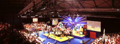 Eurobot competition.
This year, the topic of the competition was Robot Recycling Rally. The robots were supposed to sort waste. There are three kinds of waste to find: bottles, cans and batteries. The matches involve two teams and last 90 seconds. Each team is associated with a color, red or blue. There are two bins for each team: one for bottles and one for cans. In addition, there is one, shared, basket for the batteries. Each robot finds some garbage on the table, transports it to the correct bin, deposits it, and returns to look for some more garbage. The robot, which sorts more waste into correct bins will be the winner.
Hardware System Structure
Mechanic parts
 3D model of the robot.
Collecting mechanism consists of two rotating cylinders, rubber belts and a lifting door. Robot can hold four waste peaces in his built-in stack. Depositing mechanism consists of a conveyor belt and a back door. For the waste deposition, robot goes to the baskets situated in the corner of the playground. Afterwards, it uses the conveyor belt or the back door in order to eject waste from the stack depending on whether it is a bottle or a can. The figure above shows more details of the robot.
 The robot.
Electronic Parts
 Electronic Structure.
The electronic system of the robot consists of four subsystems.
The first subsystem is the main controller. As a main controller for the robot was chosen embedded board BOA 5200 from Analogue Micro. This board is based on MPC5200, a PowerPC processor by Freescale. The board features among others 10/100TX Ethernet controller, 2 x CAN controllers, serial interface, I2C interface and SPI interface. Especially presence of CAN controllers was very important for choosing this board, because we decided to go for CAN bus as a main bus for interconnecting individual subsystems in our robot. CAN is a differential bus used especially in automotive industry.
The second subsystem represents the sensoric system. All the sensors are connected to a board with Hitachi/Renesas H8S2638 processor. The processor collects data from all the sensors and sends the values to the main controller via the CAN bus.
The third subsystem is the drive controller board. This board is also based on the H8S2638 processor and contains bridges for driving the motors. Robot is powered with two brush-less DC engines by MAXON.
The last subsystem performs collecting measurements from the laser beacon, used for robot's localization. Electronic is based on a modulated laser emitter and a detector with band-pass. Data are captured and sent to a CAN bus using a board again with the H8S2638 processor.
Robot is equipped with several tens of IR sensors for waste detection, waste recognition, opponent detection and obstacle detection.
Main Control Unit
As was already mentioned above, the main control unit is based on a MPC5200 board with a PowerPC processor. The board runs Linux Kernel version 2.6.18. For the root file system we use the Journalling Flash File System version 2 or JFFS2. It is a log-structured file system for use in flash memory devices. JFFS2 supports NAND flash devices and in comparison to JFFS, it supports hard links, compression and better performance.
Since a small size of integrated flash memory (16MB), we use an efficient software called BusyBox. It is a software application which combines tiny versions of many common UNIX utilities into a single small executable. It provides replacements for most of the utilities which can be usually found in GNU fileutils, shellutils, etc. The utilities in BusyBox generally have fewer options than their full-featured GNU versions. However, the options that are included provide the expected functionality and behave very much like their GNU counterparts.
Size of the whole root file system is less than 5MB. Redboot, a famous boot loader by eCos, is installed on the board to provide means for simple kernel and file system replacement. Communication with the board is realized through serial line or on-board integrated Ethernet controller to which WiFi access point is connected.
Software Structure
Main Control Application
The program development was carried out mostly in C/C++ using free software tools and libraries. Components are designed with respect to the versatility. Main control program of the robot has been built on finite state machine architecture. We have developed a sophisticated and easy to use API to implement the state machines. By now we are using four state machine running simultaneously in separate threads. The main program consists of the main state machine for game strategy, state machine of the robot's motion, state machine of the waste collection and the last is used for the localization.
Robot motion is controlled by a layered architecture. The lowest layer comprises of PID controllers run in the driver board. On top of this, there are several layers run in the main controller. The trajectory planner layer prepares a smooth trajectory from a set of way-points and trajectory controller tries to keep the robot on that trajectory. Finally, the path planner layer finds the optimal obstacle-free path connecting two points.
During the development, we have used several components which have simplified our work in many aspects. Some of these systems, like ORTE (OCERA Real-Time Ethernet) or OMK (OCERA Make System) is described in the Documentation section.
Localization
To navigate reliably in the playing area, a robot must know where it is. Reliable position estimation is a key problem in mobile robotics. As mentioned above, the robot localization is done using a laser beacon and three passive reflectors. The laser beacon is positioned above the robot. Passive beacons are covered with reflective tape and placed on reserved supports around the playing area. Measured angles between the reflections are used to calculate robot's position. By means of a calculated position, Monte Carlo algorithm will be able to update its model of the predicted position.
Monte Carlo Localization makes use of a methods that were invented in the seventies and recently rediscovered independently for instance in the target-tracking, statistical or computer vision. Monte Carlo Localization method is a particle filter, where the probability density is represented by maintaining a set of samples, that are randomly drawn from it. By using a sampling-based representation we obtain a localization method that can represent arbitrary distributions. Thus, the method is able to localize globally a robot. Otherwise Monte Carlo Localization is able to localize a mobile robot without knowledge of its starting position, which allow robot to re-localize after a collision with obstacles or opponent robot on the playground.
In robot localization, we are interested in estimating the state of the robot at the current time. The state vector consists of the position and orientation of the robot. The probability density function is taken to represent all the knowledge we possess about the state, and from it we can estimate the current position. To localize the robot we need to recursively compute the density. This is done in two phases:
Prediction phase: In the first phase we use a motion model to predict the current position of the robot. In our case, the predicted position is done by the odometry. Odometry is the use of data from the rotation of wheels or tracks to estimate change in position over time.
Update phase: In the second phase we use a measurement model to incorporate information from sensors to correct the predicted position. In our case, the measured position is calculated using reflected angles between beacons.
The global localization capability of the Monte Carlo Localization method is illustrated in the following figures. In the first iteration, the algorithm is initialized by drawing 5000 samples representing the probability density. As the robot moves over the area, the samples are concentrated to the estimated position.
 Initialization of 5000 samples.
 Global localization after the first step.
 Estimated position after 15 steps.
Visualization
Within the project, we have developed an application used for visualization of the robot. The application shows sensor values, position of the robot and allows controlling of all subsystems of the robot.
 Robot visualization.
In addition it makes simulation of the robot behavior possible. Thus, the simulation simplifies development of algorithms, such as path planning or localization algorithm.
 Trajectory simulation.